Kaden’s Automated Coop – the backstory
I thought I had an original idea when I, as an Automation professional in the Oil & Gas business, decided to automate my son’s chicken coop. Especially when I decided to use the Arduino platform to do so. Boy was I wrong. I did a quick search on Google, and there were some pretty pimp coops out there. All of them had their various reasons as to why they decided to automate their coop, and they were all very helpful with sharing their experiences.
It started with a conversation with my son, Kaden. He asked me what I did at work. I explained to him that I made things work automatically so people could be doing other tasks, and not forget to do ones that might hurt someone or something. I used an analogy he could relate too. This part of the conversation went something like:
Me: “You know how when it is cold and snowing outside and I tell you to make sure the ‘girls’ (hens) are put up, and you really don’t want to go outside in the dark to check on them and close the coop door?”
Kaden:”Yeah. Because its really cold out.”
Me: “Right, well I could make the door open when the sun comes up, and close when its dark and the girls are safe inside automatically.”
Kaden: “When are you going to do that? Today after lunch?”
Yeah – not what I meant, but hey – he has an interest in his chickens and asking what I do for a living – so why not.
Me: “ Well I am going to start planning it all right after lunch.”
One of the sites I found, in particular was Dave Naves (http://DaveNaves.com). This gentleman did an awesome job with the documentation part. I have used a lot of his information, code, and advice to complete this project. A big shout goes out to Mr. Naves. Make sure you visit his site and thank him if you use anything I’ve done here. Although I made some changes, he was the one that jump started this project for me.
Now that you are back from reading Mr. Naves site (you need to read his site), I will start the process I went through. This is most likely going to be a long process of ups and downs, so I will break it into a series of posts (eventually), and have a separate link to the Arduino sketches, parts list, and how to, for those who are ready to jump in.
I had very little experience with the Arduino – no really – I had one for like 2 days before I found his site. I got it from a friend who no longer was needing it. It was an Arduino Mega with the POE Ethernet shield. I showed this to Kaden and he was excited. Not to see this neat little micro controller, but excited to know we were about to add features to his coop. Little did he know, we did not have all the pieces in place.
I wanted to familiarize myself with the IDE, board, and programming – plus I needed to show Kaden we could make this board do something. So, I quickly figured out that one of the onboard LED’s could be controlled easily. Oh yeah, make pin 13 blink!. We had another ‘funny’ conversation when we were doing this. The conversations will begin to give you an idea as to how my son thinks.
Me: “OK see this little thing here? It’s an LED. A very small LED – light. Like we have in our lamps around the house, but much smaller. We can make it turn on or off.
Kaden: “OK, cool?” (notice it was delivered in question format).
Me: “Let’s make it blink on for 5 seconds and then off for 5 seconds and just loop through that – over and over again”.
Kaden: “ How about we do 4 seconds on then 5 seconds off”.
Me: “OK – your the boss”
Kaden: /smile/
It blinks. We count. Success!
Moving on….
I looked over Mr. Naves site, found the parts list and Amazon was my friend. Days later, we started getting all these little parts in. Kaden was still excited, but I could see the light fading since he was not seeing anything happening out at the coop. It was all on my desk at home and all theory at this point to him. I had to make something happen quick.
I wanted to use the photo-resistors to detect when the sun was up and open the door – when the sun went down – close the door. So, we did another little test with Kaden using the flashlight as the sun. We had readings. My concern was how to format these on the LCD in a manner he would understand. That was pretty easy to do. My next concern for this scenario was, what values would the actual sun produce? I needed those ‘real world’ values so I could tune the program correctly.
I decided I needed to log the data over a period of a few days to get a decent average. To do this, I needed to see how I could get the data from the Arduino. I first had the Arduino writing to a MySQL database on my web server. However, it would only do this for a time then stop recording data. Not sure what the issue is, but I will need to work on it. I plan to use this feature in the future (more on that later) I ended up using a 32GB SD card on the ethernet shield. Found a great article on programming the SD card to create a text file with the data, and display that in HTML format. (https://startingelectronics.org/software/arduino/web-server/01-log-data/)
Here is the data it displays on the web. I should have written it a little better to display a time or something, but i know when it started, and just want to grab some data. It will log data every 6 minutes. Why 6 minutes, because it is greater than 5. The data will be easy enough to correlate later in a spreadsheet.
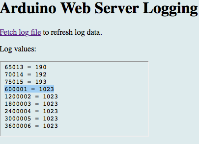
The big upside to this is the fact I won’t have to worry with programming ‘time’ into the system. I won’t have to worry with day light savings and all that stuff. I will focus on how the chickens think. Sun is up – let’s go out side – sun is down – let’s go in where its safe and roost for the night. Think like the chicken, be one with the chicken.
I got this working with my light sensor and threw into a the best container I could find that was somewhat clear. The wife won’t like it, but it is for data purposes and she can standby a couple three days or so. In the name of progress!
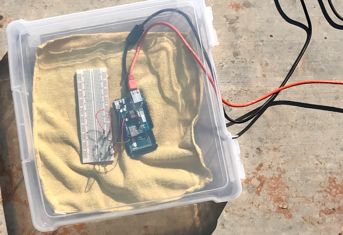
I think Kaden was expecting something more to happen than for me to carry this contraption outside and sit it on a small table in the middle of the yard. Ha! I said “OK, let’s see what kind of data we get!”. He looked at me and said, “That’s it? You’re going to leave it in the yard?”
I explained that we were going to capture data from the sun, at what time it is a certain brightness, so we could more accurately know when the girls would want out. As we were walking back in the house, my wife asked what we were doing. Kaden, walking to his room, mumbled “Dad’s catching the sun…”. I am so glad I heard that – I am the Dad who captured the sun. I told Jace, my wife, what we had been doing – not interested.
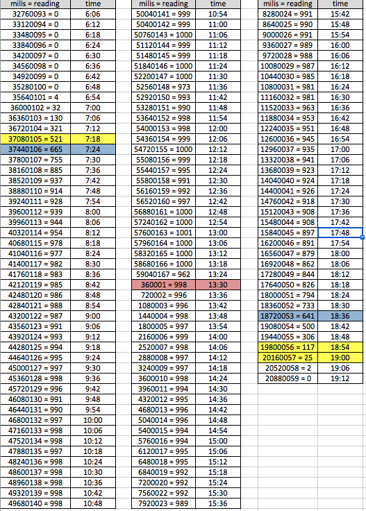
We gathered data for two days. I simply placed the data in a spreadsheet once I pulled it from the web. We even experienced a typical West Texas wind storm (30+mph winds & dust) during the testing. It actually blew the unit off a little table I had it sitting on. I saw it go over, and got it powered right back up. readings picked up right where they were since it was down approximately the same amount of time that the delay was….or that’s my theory.
The highest readings we got during the two day test were one the first day around 13:00. It registered 1003. The second day’s testing revealed that at the same time, that days readings were at the highest – registering 1001. I am only capturing the raw analog signal which is from 0 – 1023 (0-5 volts into integer values). Based off the data, I plan to make it a little more simple for Kaden to read on the web application and the LCD. The code will be something along the lines of:
// print out the value you read:
Serial.print(“Reading: “);
if (sensorValue <=100) {
Serial.print (“Dark”);
} else if (sensorValue >= 101 && sensorValue <= 499) {
Serial.print (“Dim”);
} else if (sensorValue >=500) {
Serial.print (“Bright”);
}
Basically he will see on the LCD or Display something along the lines of Dark, Dim, or Bright. So if we register a reading equal to or greater than 500 (=>500), and hold that value for a few minutes (to make sure the reading is stable and true) then the door open command will be sent. Opening the door, and allowing the girls to come out into the run.
For the darker side of things, I think it was interesting to see how quickly the light dropped off. The online weather information stated sunset was to happen at 18:39 on this day. The reading at that time was 646. Six (6) minutes later the reading then went to 500, elapse 6 minutes to 306, 6 minutes later to 117, then another 6 minutes and we are at 25. The 25 reading came in right at 1900. Somewhere between the 117 and 25 readings the girls put themselves up. I had planned on observing this more closely, but again, the family had things more important to do.
I am thinking that once we register a reading equal to or less than 25 for an amount of time – we’ll close the door. I will not try to register each chicken that passes through the door and all that – well not yet anyway. This is pretty fun, so I might.
Here is a sample of the data taken:
We now had a couple days worth of data that would allow us to determine sunrise and sunset. Now we needed to do an experiment with the motor.
I wired up the L298N driver, and a 24vDC power supply to the motor. I made the proper connections to the Arduino and wrote a quick program to allow it to turn one direction at full speed (20RPM) and then the other way at full speed. Both directions for 5 seconds. Kaden was really enjoyed this test. He told his mom, “see, this will pick the door up and let it down when we need it.”.
I was happy he was enjoying the tests, somewhat. For my inexperience I need these test to understand how each individual thing works, before I write a small program to control all the end devices based off each other.
Our next test was when the temperature sensors arrived. I ordered some water proof DS18B20’s off Amazon. They looked great and I was familiar with RTD’s and TC’s from my day job. What I was not familiar with was the color wires on the ones I received. I searched Google, but nothing came up to show me what color was what????? I had a green, yellow, and a red. I was betting red was the power, green ground, and yellow signal. I was wrong.
After a little switching of the leads I learned that the green was the signal wire, yellow the ground, and red as I originally thought. Oh, don’t forget the 4.7k resistor between the power and the signal. Important!
I found a great tutorial on these sensors as well, which really helped me get my head wrapped around the OneWire library. I was a little confused on this at first. The tutorial can be found at https://arduino-info.wikispaces.com/Brick-Temperature-DS18B20
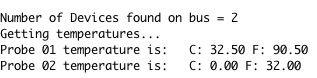
I used their sketches to determine the correct sensor leads to the Arduino. Then to determine each sensors address and temperature reading. I held one in my closed hand and put another in ice water. Here is a screen shot of the readings.
So – all these tests – whats next? More tests of course. The next test will be the relay test. I want to make sure I have an understanding of everything before I move forward as I said. Even though its just a relay, I want to make sure I know how to control it with the Arduino first.
We will use a lamp, and see if we can turn it on and off via temperature. Just for fun
Things still to be completed: (in random order)
- build a pulley/spool for the motor
- redesign the door as a unit we can just install on the coop
- install reed switches in the door unit
- housing for motor
- the controller box
- LCD bevel to protect it from the weather
- LED/Light indications so we can see the status of the door or controller
- Web site to control it all and to monitor data
- build the feeder
- build the waterer
- Obviously wire the coop for control
- …and more!
https://splice.gopro.com/v?id=6o3A5x